Some will find this article interesting
Rick
ve3iqz
Best Placement of a Mobile Antenna
Don’t Lopside Your Pattern!
Source: Larsen Amateur Catalog (PDF) - Written by
Aaron Logan.
We have provided you some guidelines for mobile antenna
selection. When selecting a mobile antenna, there are a number of
factors that significantly affect the ultimate performance of the
antenna. Gain requirements, electrical type, ground plane
availability mounting style and placement, coaxial type and loss
ratings, physical size, appearance, and surrounding environment
are all issues that must be addressed to ensure the maximum
performance from a mobile antenna installation. The electrical
type or design of the mobile antenna is commonly referred to in
terms of its dimensions in terms of wavelength: 1/4 wave, 1/2
wave, 5/8 wave, etc. Each electrical type has a specific radiating
pattern to be considered when selecting a mobile antenna. For
example, the signal radiating from a 1/4 wave antenna is directed
more vertically, thus making it ideal in urban environments where
buildings might obstruct the signal. The design of a 5dB collinear
mobile antenna is designed to direct the signal more towards the
horizon. This type of antenna is ideal for geographically flat
regions where signal coverage is sparse.
 Ground plane availability
is another critical factor in mobile antenna performance, and must
be considered when determining the location and type of the
antenna. Ground plane requirements vary given the type of mobile
antenna and the frequency of operation. A typical 5/8 wave antenna
at 150 MHz requires a ground plane of at least 42” in diameter. At
450 MHz, 15” is required, and 800 MHz, a minimum of 8” is
considered sufficient.
Ground plane availability
is another critical factor in mobile antenna performance, and must
be considered when determining the location and type of the
antenna. Ground plane requirements vary given the type of mobile
antenna and the frequency of operation. A typical 5/8 wave antenna
at 150 MHz requires a ground plane of at least 42” in diameter. At
450 MHz, 15” is required, and 800 MHz, a minimum of 8” is
considered sufficient.
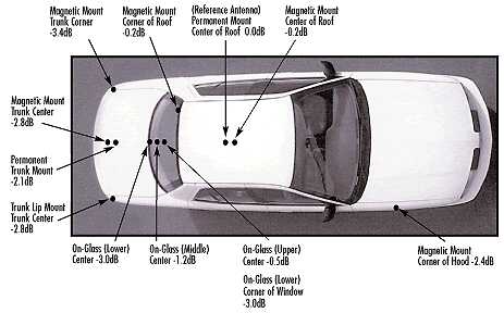
In terms of mounting mobile antennas on a vehicle, there are five
general locations: the roof, front fender, rear fender, trunk and
rear window glass (although other glass mount locations may be
used). Of these, the center of an automobile roof is considered
the best for mobile antenna placement, followed by the center of
the trunk lid, the fenders, and then on-glass mounting. This
ranking is determined by the amount of ground plane provided by
the positioning, and clearance from obstruction (i.e.: the roof
line), and is the reason the center of the roof is considered the
ideal mounting location, provided the roof is metal. The diagram
above illustrates the effective loss (at 800 MHz) due to
insufficient symmetrical ground plane.
2002: found at
alfenterprises.com/AntennaIndexCategory.html (dead link); 2015:
located source in Larsonn Amateur Catalog; 2016: Author located!
It is the policy of kv5r.com to properly credit all sources,
when possible. This one just took a while!
From the Author of the article:
Testing was completed at the Larsen Antenna manufacturing site in Vancouver, WA. This testing was done in an outdoor test field, multiple wavelengths from nearest buildings and structures in a controlled environment.
This information is directly from the Larsen catalog. (I wrote it while employed at Larsen – know Pulse Electronics.)